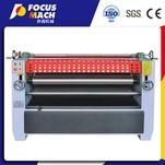
Double-roll glue coating machine
The structure of the double-roll glue coating machine is shown in Figure 2, which is mainly composed of a frame, a glue coating roller, a glue tank and a transmission device. The frame 1 is made of casting or steel welding, one on each side, and the middle is connected by a tie rod bolt 2 to form an integral frame to ensure its stability. The frame is used to support components such as the glue coating roller, the glue tank and the transmission device. The glue coating roller is divided into an upper glue coating roller 3 and a lower glue coating roller 4, which are made of cast iron or steel pipes. The outer surface of the roller is coated with hard rubber and has grooves on the surface. The diameter of the rubber roller is 200 to 300 mm, usually not exceeding 350 mm. The shapes of the grooves on the surface of the roller include straight thread, various grid shapes and horizontal stripes, and the straight thread shape is the most used. The number of grooves of the straight thread is generally 20 per inch (25.4 mm), the pitch is 1.27 mm, and the groove depth is 1 mm. The number and depth of the grooves of the glue roller have a great influence on the amount of glue applied. The denser and shallower the grooves, the smaller the amount of glue applied.
The glue groove 7 is installed below the lower glue roller and is welded from steel plates. The lower glue roller is partially immersed in the glue in the glue groove to bring up the glue to glue the veneer. There is a row of small rollers that can rotate automatically on the side wall of the glue groove to support the glued veneer to keep it horizontal so that it does not touch the groove wall and scrape off the glue under the veneer. The transmission of the double-roller glue coating machine is driven by the motor 9 and connected to the lower glue roller through the reduction box 8. The transmission from the lower glue roller to the upper glue roller is transmitted through a pair of long-toothed gears (or sprockets) on the shaft ends of the upper and lower glue rollers. The function of the long-toothed gear is to ensure its normal transmission when moving the upper glue roller to adjust the gap between the glue rollers. The hand wheel is used to adjust the gap between the glue rollers. The screw is connected to the bearing of the upper glue roller. When the hand wheel is rotated, the screw rotates to move the upper glue roller up and down to adapt to the changes in the thickness and glue amount of the single board.
Four-roller glue coating machine
The structure of the BS3414 four-roller glue coating machine is shown in Figure 3. It mainly consists of a frame, an upper glue coating roller, a lower glue coating roller, an upper squeeze glue roller, a lower squeeze glue roller, an adjustment mechanism, a transmission device, a cleaning tank and a glue supply system.
1) Frame.
The frame 12 of the four-roller glue coating machine is divided into two parts, which are cast or welded by steel plates; the left and right frames are connected as a whole by upper and lower beams and fixed to the foundation with anchor bolts. A two-speed motor 11 and a cycloidal pinwheel reducer 10 are installed on the bottom plate. The transmission system is enclosed in the left and right frames, and a maintenance door is installed on the outside. There is an upper glue coating roller lifting mechanism on the upper part of the frame, two handwheels for adjusting the upper squeeze glue roller and a gearbox operating handle at the front, and two handwheels for adjusting the lower squeeze glue roller at the rear.
2) Glue coating roller and glue squeezing roller.
The four-roller glue coating machine has upper and lower glue coating rollers 5, 7 and upper and lower glue squeezing rollers 4, 8. The upper and lower glue coating rollers coat the glue on the upper and lower surfaces of the single board while conveying the single board. The structure of the upper and lower glue coating rollers is basically the same. Two layers of hard rubber are coated on the thin-walled cylindrical surface of the glue coating roller. The thickness of the inner and outer rubber layers is 10 mm. The surface hardness (Shore) of the outer rubber layer is HA95, the hardness of the inner layer is HA45, and the hardness unevenness is HA4. According to the different types of rubber used, grooves of certain shapes and sizes are processed on the surface of the glue coating roller, which is an important factor affecting the quality of glue coating. The journals at both ends of the glue coating roller are installed in the bearings, the bearing seat of the lower glue coating roller is fixed on the frame, and the bearing seat of the upper glue coating roller is installed on the slide of the lifting device. A sprocket is installed at one end of the glue coating roller to drive it to rotate, and a gear is installed at the other end to drive the squeeze roller to move. Increasing the diameter of the glue roller is conducive to extending its life and improving the uniformity of glue coating, but it increases the size and mass of the machine tool accordingly. Therefore, the diameter of the glue roller is generally 250-400 mm. The function of the glue squeezing roller is to control the amount of glue coating. Its structure is similar to that of the glue roller, but the surface of the thin-walled cylinder is not coated with rubber, but chrome-plated and polished. The diameter of the glue squeezing roller is generally 150-300 mm.
3) Transmission device.
The upper and lower glue rollers and the glue squeezing roller are driven to rotate by a two-speed motor 11 through a cycloidal pinwheel reducer 10, a two-stage variable speed sliding gear and a sprocket drive, and an automatic tensioning device is provided to tension the transmission chain. In order to meet the needs of different veneers and types of glue, four-roller glue coating machines mostly use a two-speed motor combined with a speed change mechanism to obtain a variety of speeds to improve production efficiency. The highest glue coating speed has reached 100 m/min. The rubber roller is driven by the gear on the rubber roller shaft through two pinions and a large gear mounted on the end of the rubber roller shaft, so that the linear speed of the rubber roller is lower than that of the rubber roller, which plays a role in scraping glue. One of the two intermediate pinions is fixed, and the other is connected to the large gear on the rubber roller by a connecting rod, so that it can still be properly meshed when the position of the rubber roller is changed.
4) Upper rubber roller lifting device.
The gap between the upper and lower rubber rollers should be adjusted according to the thickness of the veneer so that the pressure on the veneer is 0.15-0.25 MPa. The bearing seat of the upper rubber roller is mounted on the left and right slides 14 and 4. The hand wheel 1 is operated to drive the left and right slides to move up and down along the guide rail through two pairs of worm gears 8, worm 3 and lead screw 6 to adjust the gap between the upper and lower rubber rollers. The pressure of the rubber roller on the veneer is adjusted by adjusting the nut 12 and changing the pressure of the spring 13.
5) Rubber roller adjustment device.
The rubber roller adjustment device is used to adjust the gap between the rubber roller and the rubber roller to control the amount of glue. The bearing seat 6 of the rubber squeezing roller 7 is installed in the slide 9, and the slide is fixed to the frame with bolts 10. The hand wheel 1 is turned to adjust the bearing seat to move the rubber squeezing roller. The hand wheel has a dial 11 to indicate the adjustment amount. The top force of the rubber squeezing roller is determined by the spring 4, and the spring pressure can be changed by rotating the adjustment sleeve 3. When the rubber squeezing roller and the rubber coating roller are squeezed too tightly, the rubber squeezing roller will be overloaded, and the overrunning clutch installed at the end of the rubber squeezing roller shaft will slip to avoid the transmission chain.
6) Other devices.
A glue pumping device is provided above the four-roller glue coating machine, which can be adjusted according to the actual glue consumption. The glue is stored in the groove between the glue coating roller and the rubber squeezing roller; to prevent the glue from overflowing, the two ends of the glue coating roller and the rubber squeezing roller are equipped with a rubber baffle and compressed by a spring. The degree of compression can be adjusted by adjusting the spring compression device. The cleaning tank 9 is welded with steel plates and installed below the lower rubber coating roller to remove sewage after washing the rubber roller. A safety switch is also installed on the crossbeam at the front end of the four-roller glue coating machine. When a fault occurs, pressing the switch will stop the machine immediately to ensure safety.